Страница: 7/10
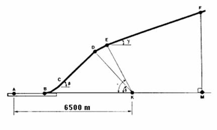
Figure 6.2 Take-off and climb path
The take-off profile is defined by five parameters -- (A) AB, the length of take-off roll; (B) β the first constant climb angle; (C) γ, the second constant climb angle; and (D) δ, and e, the thrust cutback angles. These five parameters are functions of the aircraft performance and weight, and the atmospheric conditions of temperature, pressure, and wind velocity and direction.
Under reference atmospheric conditions and with maximum take-off weight, the gradient of the second constant climb angle (γ) may not be less than 4 percent. However, the actual gradient will depend upon atmospheric conditions, assuming maximum take-off weight and the parameters characterizing engine performance are constant (rpm, or any other parameter used by the pilot).
In operational conditions the climb is performed without the cutback stage, and the aircraft flies over the control point at a lower altitude, which leads to higher noise levels.
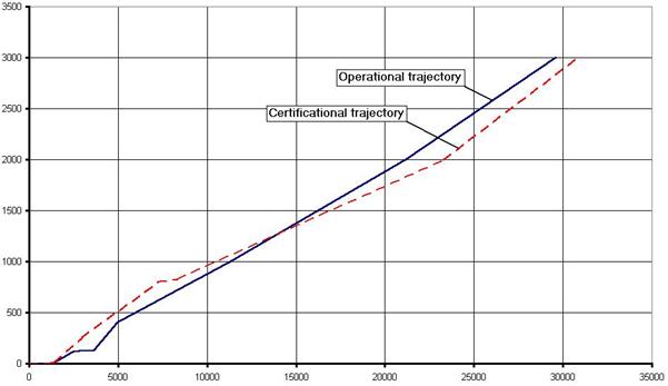
Figure 6.3 Comparison between operational and certification trajectories
The climb path for Tupolev 154M was calculated using the following equation

where:
m is aircraft mass;
P is thrust;
a is the angle of attack, j is the angle of engine installation;
q is climb angle which is equal to b or g, depending on the climb stage.
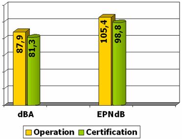
Figure 6.4 Comparison between noise levels under different flight paths
6.2.2 Approach Noise Calculation
The approaches must be conducted with a steady glide angle of 3°±0.5° and must be continued to a normal touchdown with no airframe configuration change. Thus the distance from the control point to the glideslope RN remains constant and is equal to 119.7 m.
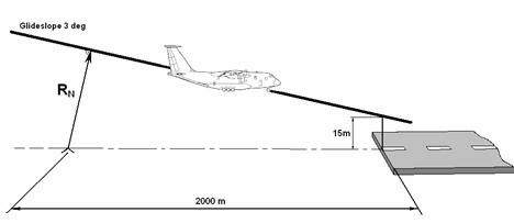 |
Figure 6.5 Schematic of approach
Taking into account that the speed remains constant and airframe configuration is for landing, we can calculate the stall speed:
 ,
,
where G is airplane weight, r is air density, S is wing area, Cy max is maximum lift coefficient determined from Fig. 6.6.
Approach speed should be 30% greater that the stall speed:
![]()
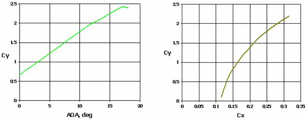
Figure 6.6 Aerodynamic characteristics of Tupolev 154M.
Using the approach speed, we can calculate current lift coefficient:
![]() .
.
Corresponding drag coefficient is determined from Fig. 6.6.
Some corrections must be made to calculated values of drag and lift coefficients. It is necessary to take into account the influence of the landing gear which creates additional drag and decreases lift. The influence of flaps and slats is little and can be neglected.

Necessary thrust is calculated using the following formula
![]() ,
,
where  is drag and q is approach path angle which is equal to 3 degrees.
Calculated results for five different landing weights are shown in the table 6.3.
Table 6.3 Calculation results for Tupolev 154M at approach configuration.
|
Weight, % MLW |
MLW |
95% |
90% |
85% |
80% |
|
Weight, kg |
80000 |
76000 |
72000 |
68000 |
68000 |
|
Vapp, m/s |
74,8 |
72,91 |
70,964 |
68,965 |
66,91 |
|
Thrust, kg |
8445,63 |
8024,67 |
7601,88 |
7179,66 |
6758,58 |
|
LA, dBA |
96,74 |
96,05 |
95,35 |
94,66 |
93,97 |
|
EPNL, EPNdB |
112,17 |
111,32 |
110,48 |
109,64 |
108,79 |
|
∆LA, dBA |
0 |
0,69 |
0,7 |
0,69 |
0,69 |
|
∆EPNL, EPNdB |
0 |
0,85 |
0,84 |
0,84 |
0,85 |
|
SQRT (Wing Load) |
21,082 |
20,548 |
20 |
19,437 |
18,856 |
|
Thrust To Weight rt. |
0,10557 |
0,105588 |
0,105582 |
0,105583 |
0,105603 |
Реферат опубликован: 28/08/2007